Sunday, February 25, 2018

Lathe Upgrade: Metal Gear Transmission

Although the Harbor Freight mini-lathe is reasonably well built, I did find the plastic gear transmission to be less than strong enough.

The dust of shredded gears...
The broken gears, note the missing tooth on the small gear, and the crack running through the large gear.


I will add here that although I did wind up breaking the gears, I did a lot of reading online, and there were plenty of people who have owned the lathe for many years and never had any issue with the plastic gears.  I opted to get the more expensive metal gears knowing that I planned on turning some other harder metals (such as titanium) and I am awfully impatient and will wind up making deeper cuts than I should...

Metal Transmission Gear Set from Little Machine Shop
In any case, I decided to bite the bullet and get the metal transmission gears from Little Machine Shop.

Although installing the gears does require extensive disassembly of the lathe (the motor has to be loosened from its mounts to get access to the headstock bolts, the electronics has to be removed. the chuck and spindle must also be removed, etc...)  it was not difficult, only time consuming.  I removed the shafts with a lead hammer to avoid marring them, and was able to not lose the Jesus clips holding them on (is there anything more satisfying than that?).

I also loaded up the new metal gears and the change gears with a good grease.  At some point I want to add a pair of Zerk fittings to the top of the headstock so that I can squirt in more grease whenever the mood strikes me.

The new metal gear transmission is much smoother (funny how when a gear has all of its teeth it runs better...), but it is noticeably louder.  I am very pleased with the upgrade.  Although many people may never need to replace their gears, I am the type that gets bored too easily to avoid biting off a bigger chip than I can cut, so I know the metal gears will be well worth it in the long run.

Monday, February 19, 2018

New Tool Review: Harbor Freight Mini-Lathe

I've wanted my very own lathe for quite a long time now, but I never really had a significant specific need for one (other than just to have one), nor have I had the budget for one.

Some of the projects I have been working on lately required lots of round metal parts, and having been reading a lot about different lathes, I decided it was finally time to get myself a lathe.

Without the space or budget for a full size lathe, I looked at the mini-lathes available and quickly learned that essentially every single mini-lathe on the market today is essentially the same.  The primary distinguishing feature between the different brands of mini-lathe is the color, not kidding.

This means that there is a massive online community of support and upgrades for these lathes.  My biggest fear was that I would get the lathe, and quickly find its limits/faults and be left with an expensive tool that was a disappointment and I could do nothing with.  This is not the case at all.  There are hundreds, if not thousands, of videos and tutorials on how to get the most out of the lathe, and there are loads of improved and replacement parts available online.  Armed with that knowledge I decided to buy one of the 7x** mini-lathes.

With my limited budget I decided to go for the 7x10 lathe from Harbor Freight (don't forget your 20% off any one item coupons!)  Although it is the smallest 7x** lathe, I was not concerned given the size of the work I planned on doing, and the knowledge that I could upgrade every part of the machine if I so desired, up to and including extending the bed to 7x16.

Along with the lathe I purchased the HSS tool set, the indexable carbide tool set, and the MT2 drill chuck for the tailstock.

Harbor Freight 7x10 Mini-Lathe

On arrival, I was very pleased with the overall feeling of the machine.  Unlike most of the things you get from Harbor Freight, this machine has a nice heavy feel to it.  The vast majority of the machine is cast iron and as a result does not leave you with that cheapo plastic-y feeling.  My biggest complaint initially was the preservative anti-rust stuff they cover the whole thing it.  It is yellowish, sticky, and absolutely gross.  I should have followed the other suggestions online to immediately take the entire machine apart and clean it with alcohol or some other solvent before using it, but frankly I was just too excited to try it out first.  If you don't do this first, chips will get mixed into the stuff and make it impossible to vacuum them up and even harder to clean the stuff off of the machine when you finally get sick of it being everywhere.


This drill chuck from HFT is awful...  Don't waste your money


However, the MT2 drill chuck is terrible.  The MT2 taper part is not ground and has the surface finish of the moon.  Furthermore, the full size MT2 taper is too long for the tailstock and forces a minimum 1/2 in. extension of the tailstock to hold it.  In addition, although the JT33 taper where the chuck mounts looks OK, either the chuck or the taper is incorrectly sized and the chuck wobbles around on
the taper.  A total waste of money.

I recommend getting the short taper one from Little Machine Shop.


A good QCTP: All steel, 0XA wedge type, and with a flat parting tool holder

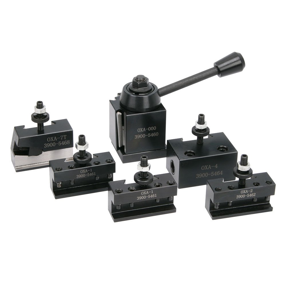
Also, do not buy the quick change tool post (QCTP) from Harbor Freight, as it is incompatible with Aluminum ones or the "button type" steel ones are not very good.
any other tool holders, much better off getting a 0XA QCTP from Little Machine Shop.  I bought one of the steel wedge type ones after reading that the

Unfortunately, the one I bought from Amazon has an angled parting tool holder that raises the end of the parting tool too high.  Little Machine Shop sells one that is flat and will work with the 7x** lathes.


The Harbor Freight tooling has been excellent.  I have no complaints about the indexable carbide or HSS tools.

The machine was tuned in enough to cut aluminum with little trouble right out of the box.  I started working on the first few parts I wanted to make to both test out the machine, and get working on my project.

However, I had a problem within 30 minutes of running the lathe...

The back side of the apron is left completely open, exposing the carriage hand-wheel gear train to all of the chips that fall out of the machine.  This area immediately clogged up and caused the gears to jam up and made operating the lathe a real pain.  Thankfully, the included tool set has almost every tool you need to work on the machine (minus a couple small metric hex keys, and a Phillips screwdriver).

Oh, yeah, that reminds me, I should mention: All of the parts on the machine are metric, but it is set up to make stuff in Imperial units.  The dials are all in .001" and the change gears are for cutting inch standard threads.  Metric conversions are available.

So, I decided it would be best at this point to dissemble the lathe and do the full clean-up, greasing, and make a little cover for the apron.

I dissasembled the entire carriage and apron so I could clean and grease all of the parts.  I also found this stuff by WD-40 which claims to protect against any rusting for at least a year.

WD-40 Corrosion Inhibiting Spray
I purchased it at Home Depot for $12, which is a bit expensive, but if it works, it'll be totally worth it.  All you do is spray it on and wipe off the excess.  Tee nice thing is that it doesn't leave an oily residue after it dries, so chips easily vacuum off.  Any metal surfaces that I didn't grease got treated with that, and so far no rusting, but we'll see how it holds up in a years time.

Anyhow, back to the lathe.  I made the little cover for the apron out of a thin piece of polycarbonate I had lying around.  I just traced the outline of the gears onto the plastic, cut it with aviation shears, and then mounted it by drilling and tapping a hole for an M3 screw in the apron. (See photo below)  The gears rub on the plastic a bit, but it works fine for me.

Custom plastic chip guard

Since installing the chip guard, I have had no problem with the gears jamming.

After this I greased up the ways and reassembled the whole machine.

I was able to turn 2.25 in. 6061 aluminum without making any other adjustments to the machine, and still get a decent surface finish.  It was chatter-y, but I didn't feel like dealing with adjusting the gibs yet.


First chips, turning 2.25 inch aluminum


So that was my first few days with the mini-lathe.  That was back the first week of January, and I have used the machine almost every day since then. I am extremely happy with it.  For a "My First" lathe I couldn't ask for more.  It is low cost, a convenient size, and infinitely upgradable.  It has been an excellent machine to learn on, and learn about.  Overall, I am extremely pleased, but I will add that I bought the machine with the knowledge that it would have its issues, and wouldn't be perfect right out of the box.  If you want a lathe that is a perfect machine right out of the box that you will never have to touch, tweak, or fix, this is not the machine for you.  It will have some issues, and they will need to be fixed, but if you are accepting of this, you will not be disappointed.

Since this post is already getting pretty long, I'll end it here.  I'll be writing more posts over the next few days about the upgrades I have already done, and the problems/solutions I have had the lathe so far.

Friday, September 1, 2017

Waiting, waiting, waiting...

After all of the excitement of the Kickstarter campaign, it almost feels as though the project has been forced to grind to a halt. Although some construction work has continued, most of the past two weeks following the end of the Kickstarter have just been waiting. First off, Kickstarter takes 14 days to process the funds themselves. It was only yesterday that I got the confirmation that they were transferring the funds to my bank. Now I get to wait a couple days for my bank to process the funds and have them show up in my account. Then I will finally get to start ordering parts and supplies for the capsule, after which point I will once again wait for their arrival. But then... Then... The fun begins! Then it will finally be time to start building the greatest Kerbal Kontroller of all time! Soon... Soon...

Thursday, August 17, 2017

We have liftoff!

The Open Source Gemini Simulator has achieved liftoff! The project reached its goal of $1,675 with less than 45 minutes remaining in the campaign! Thanks to all who backed the project! The Kickstarter will continue to get updates as the project is built, but the primary source for updates will be here; Ventures in Making. I will be writing a couple of lengthy posts talking about my first time experience with Kickstarter in the next few weeks, it has been quite an eye-opening experience.

Friday, August 11, 2017

OSGS Update: The Controls List

As we come into the final 5 days of the Open Source Gemini Simulator Kickstarter campaign, I have finalized the list of controls to be placed in the capsule, and I am ready to release them.

I have spent numerous hours carefully documenting all of the controls one would want in a KSP sim-pit with the intent of enabling the players to perform nearly all of the functions of the game without needing a keyboard or mouse.  Below is the full, comprehensive list of controls, what type they are, their location, and notes on how it will work in the game.

After deciding what controls would be in the cockpit, it was time to start working on the layout of the controls.  For this I went directly to Gemini Guide and the Gemini familiarization manual to try and recreate the "feel" of the original Gemini capsule.  Obviously, there are many controls needed in the Gemini capsule that are not needed in KSP, and many controls needed for KSP that were not needed for Gemini.  Despite this complication, I made my best effort to preserve the "spirit" of the Gemini capsule by placing similar controls to their real life counterparts in KSP.

The greatest change to the look and feel of the Gemini capsule will be the addition of a screen on which the game is displayed.  To accommodate the largest screen possible, I decided to place it on the center cockpit panel (see picture below, the area outlined in red is the approximate shape and location of the screen)


Much of the center console is dedicated to the communications/radios and life support systems found in the Gemini capsule.  Given that KSP has minimal implementation for communications/radios and life support (yes, there are mods that do it, but not in the stock game, and I didn't want to complicate this capsule any more than it already is, more controls can easily be added later), I decided to eliminate much of these controls and replace them with the screen.

The physical controls are located mainly on a few major panels, the overhead panel, the right and left panels, and the center console.  Most of the controls are switches, just like in the real Gemini spacecraft, though I have opted for lighted toggles because who doesn't love blinking LED lights?
Anyhow, without further ado... The full control list:

Wednesday, August 9, 2017

Less Than 10 Days on Kickstarter and Navball Design

It's been quite a while since I posted an update due to life getting very busy with the Kickstarter, but with less than 10 day s left I felt I should really get around to posting an update.  Here is an in depth update on the navballs.

One of the most complex parts of the project is the design of the two 3 axis navballs.  The navballs (also know as FDAI, or Flight Director and Attitude Indicator) are a key part of the project, and will be a valuable addition to the standard flight instruments.  Of course, I could have gone with a small screen and some graphics to simply display a navball, but the excitement of have a truly mechanical navball was simply too much.

The first step to designing the navball was to create the 3-axis drive system and frame.  This would consist of the ball itself and the three stepper motors to go with.  As described in this KSP forums thread about creating a mechanical navball ([WIP] The REAL Nav Ball Project Thread (2017 Edition)) two of the steppers are located inside of the ball itself.

I decided on a 5" diameter ball, this gave me enough room to locate two small stepper motors comfortably inside without needing any sort of gear-train.  The navball requires almost no torque to operate, therefore, I could use the smallest readily available stepper motors, NEMA 8 size motors. One of the motors would need a dual shaft to support both sides of the navball.

One major alteration to the design described in the KSP forum thread will be the orientation of my ball.  Instead of having the stationary center ring located vertically, this design is positioned horizontally. This makes 3D printing the ball halves simpler because each half can be printed in a single color.

The roll motor had to be mounted on a gear because of the need for a slip ring to pass through the center of rotation.  Not wanting to resort to using extremely expensive slip rings with shaft pass through capability, I decided to simply use a 3D printed herringbone gear to drive the roll axis.  This was not a problem for the yaw axis because it supported from both sides, therefore the slip ring is located on the side opposite the stepper.

This was actually the simplest part of the design process, the needles ended up taking far more time and thought to create.

For the purposes of my navballs, I decided to include two flight director needles, enabling the pilot to display two different "nodes" at a given time.  This dramatically eases the process of docking due to the need to see both the prograde and target vectors at the same time.  At first, the needles seem like a very simple setup.  The needles only need to rotate about one axis each, so they can easily be attached to a servo that will rotate them up and down, (or left and right).

Initially, I went with this design, also including full length needles that will be the length of the navball.  This idea was quickly written off because I realized the needles would collide with one another.  When the needles move they rotate, and therefore also move "in and out" relative to the face of the navball.  This could lead to a situation where if the needles crossed in one of the corners, that one needle could essentially get "stuck" behind the other. 

Of course, there are ways to alleviate this problem including:

  • Angling the tips of the needles to conform the the shape of the ball
  • Lengthening the axis to "linearize" the motion of the needles 
  • Shortening the needles so that they overlap less.  
  • Increasing the spacing between needles so that they never cross paths
I did some research to try and see how this problem was resolved on real navballs, and it seems that the engineers simply optimized those four parameters to eliminate the problem.

 For my purposes, I decided on another option, to just simply make the needles move linearly.  This way, no needle could ever get "stuck behind" another needle, without needing to do a lot of design finagling to ensure the needles never collide.

The needles slide in a pair of slots on the side of the navball face and are moved by the servo pushing on the needle against a spring.  This way the full range of the servo is used, and the spring eliminates any hysteresis from the mechanism.
The below pictures represent the current state of the navball design.


This pretty much covers the design of the navballs.  I'll try to post at least a couple more updates before the Kickstarter ends, but that is no guarantee.  Once again, any support on the Kickstarter is massively appreciated! Find the project here: Open Source Gemini Simulator

Tuesday, July 18, 2017

Kickstarter is LIVE!

Great news! The Open Source Gemini Project is now live on Kickstarter!
The project is a 30 day project, and I will be posting updates throughout the Kickstarter process.  I sure have learned a lot already with my first Kickstarter project, and it has only just gone live.  When it is all finished, I will be sharing my experiences here.