
A place to document my trials and tribulations in my quest to make cool stuff.
Friday, September 1, 2017
Waiting, waiting, waiting...
After all of the excitement of the Kickstarter campaign, it almost feels as though the project has been forced to grind to a halt.
Although some construction work has continued, most of the past two weeks following the end of the Kickstarter have just been waiting.
First off, Kickstarter takes 14 days to process the funds themselves. It was only yesterday that I got the confirmation that they were transferring the funds to my bank. Now I get to wait a couple days for my bank to process the funds and have them show up in my account. Then I will finally get to start ordering parts and supplies for the capsule, after which point I will once again wait for their arrival.
But then...
Then...
The fun begins! Then it will finally be time to start building the greatest Kerbal Kontroller of all time!
Soon...
Soon...
Thursday, August 17, 2017
We have liftoff!
The Open Source Gemini Simulator has achieved liftoff! The project reached its goal of $1,675 with less than 45 minutes remaining in the campaign!
Thanks to all who backed the project!
The Kickstarter will continue to get updates as the project is built, but the primary source for updates will be here; Ventures in Making.
I will be writing a couple of lengthy posts talking about my first time experience with Kickstarter in the next few weeks, it has been quite an eye-opening experience.
Friday, August 11, 2017
OSGS Update: The Controls List
As we come into the final 5 days of the Open Source Gemini Simulator Kickstarter campaign, I have finalized the list of controls to be placed in the capsule, and I am ready to release them.
I have spent numerous hours carefully documenting all of the controls one would want in a KSP sim-pit with the intent of enabling the players to perform nearly all of the functions of the game without needing a keyboard or mouse. Below is the full, comprehensive list of controls, what type they are, their location, and notes on how it will work in the game.
After deciding what controls would be in the cockpit, it was time to start working on the layout of the controls. For this I went directly to Gemini Guide and the Gemini familiarization manual to try and recreate the "feel" of the original Gemini capsule. Obviously, there are many controls needed in the Gemini capsule that are not needed in KSP, and many controls needed for KSP that were not needed for Gemini. Despite this complication, I made my best effort to preserve the "spirit" of the Gemini capsule by placing similar controls to their real life counterparts in KSP.
The greatest change to the look and feel of the Gemini capsule will be the addition of a screen on which the game is displayed. To accommodate the largest screen possible, I decided to place it on the center cockpit panel (see picture below, the area outlined in red is the approximate shape and location of the screen)

Much of the center console is dedicated to the communications/radios and life support systems found in the Gemini capsule. Given that KSP has minimal implementation for communications/radios and life support (yes, there are mods that do it, but not in the stock game, and I didn't want to complicate this capsule any more than it already is, more controls can easily be added later), I decided to eliminate much of these controls and replace them with the screen.
The physical controls are located mainly on a few major panels, the overhead panel, the right and left panels, and the center console. Most of the controls are switches, just like in the real Gemini spacecraft, though I have opted for lighted toggles because who doesn't love blinking LED lights?
Anyhow, without further ado... The full control list:
Wednesday, August 9, 2017
Less Than 10 Days on Kickstarter and Navball Design
It's been quite a while since I posted an update due to life getting very busy with the Kickstarter, but with less than 10 day s left I felt I should really get around to posting an update. Here is an in depth update on the navballs.
One of the most complex parts of the project is the design of the two 3 axis navballs. The navballs (also know as FDAI, or Flight Director and Attitude Indicator) are a key part of the project, and will be a valuable addition to the standard flight instruments. Of course, I could have gone with a small screen and some graphics to simply display a navball, but the excitement of have a truly mechanical navball was simply too much.
The first step to designing the navball was to create the 3-axis drive system and frame. This would consist of the ball itself and the three stepper motors to go with. As described in this KSP forums thread about creating a mechanical navball ([WIP] The REAL Nav Ball Project Thread (2017 Edition)) two of the steppers are located inside of the ball itself.
I decided on a 5" diameter ball, this gave me enough room to locate two small stepper motors comfortably inside without needing any sort of gear-train. The navball requires almost no torque to operate, therefore, I could use the smallest readily available stepper motors, NEMA 8 size motors. One of the motors would need a dual shaft to support both sides of the navball.
One major alteration to the design described in the KSP forum thread will be the orientation of my ball. Instead of having the stationary center ring located vertically, this design is positioned horizontally. This makes 3D printing the ball halves simpler because each half can be printed in a single color.
The roll motor had to be mounted on a gear because of the need for a slip ring to pass through the center of rotation. Not wanting to resort to using extremely expensive slip rings with shaft pass through capability, I decided to simply use a 3D printed herringbone gear to drive the roll axis. This was not a problem for the yaw axis because it supported from both sides, therefore the slip ring is located on the side opposite the stepper.
This was actually the simplest part of the design process, the needles ended up taking far more time and thought to create.
For the purposes of my navballs, I decided to include two flight director needles, enabling the pilot to display two different "nodes" at a given time. This dramatically eases the process of docking due to the need to see both the prograde and target vectors at the same time. At first, the needles seem like a very simple setup. The needles only need to rotate about one axis each, so they can easily be attached to a servo that will rotate them up and down, (or left and right).
Initially, I went with this design, also including full length needles that will be the length of the navball. This idea was quickly written off because I realized the needles would collide with one another. When the needles move they rotate, and therefore also move "in and out" relative to the face of the navball. This could lead to a situation where if the needles crossed in one of the corners, that one needle could essentially get "stuck" behind the other.
Of course, there are ways to alleviate this problem including:
For my purposes, I decided on another option, to just simply make the needles move linearly. This way, no needle could ever get "stuck behind" another needle, without needing to do a lot of design finagling to ensure the needles never collide.
The needles slide in a pair of slots on the side of the navball face and are moved by the servo pushing on the needle against a spring. This way the full range of the servo is used, and the spring eliminates any hysteresis from the mechanism.
The below pictures represent the current state of the navball design.


This pretty much covers the design of the navballs. I'll try to post at least a couple more updates before the Kickstarter ends, but that is no guarantee. Once again, any support on the Kickstarter is massively appreciated! Find the project here: Open Source Gemini Simulator
One of the most complex parts of the project is the design of the two 3 axis navballs. The navballs (also know as FDAI, or Flight Director and Attitude Indicator) are a key part of the project, and will be a valuable addition to the standard flight instruments. Of course, I could have gone with a small screen and some graphics to simply display a navball, but the excitement of have a truly mechanical navball was simply too much.
The first step to designing the navball was to create the 3-axis drive system and frame. This would consist of the ball itself and the three stepper motors to go with. As described in this KSP forums thread about creating a mechanical navball ([WIP] The REAL Nav Ball Project Thread (2017 Edition)) two of the steppers are located inside of the ball itself.
I decided on a 5" diameter ball, this gave me enough room to locate two small stepper motors comfortably inside without needing any sort of gear-train. The navball requires almost no torque to operate, therefore, I could use the smallest readily available stepper motors, NEMA 8 size motors. One of the motors would need a dual shaft to support both sides of the navball.
One major alteration to the design described in the KSP forum thread will be the orientation of my ball. Instead of having the stationary center ring located vertically, this design is positioned horizontally. This makes 3D printing the ball halves simpler because each half can be printed in a single color.
The roll motor had to be mounted on a gear because of the need for a slip ring to pass through the center of rotation. Not wanting to resort to using extremely expensive slip rings with shaft pass through capability, I decided to simply use a 3D printed herringbone gear to drive the roll axis. This was not a problem for the yaw axis because it supported from both sides, therefore the slip ring is located on the side opposite the stepper.
This was actually the simplest part of the design process, the needles ended up taking far more time and thought to create.
For the purposes of my navballs, I decided to include two flight director needles, enabling the pilot to display two different "nodes" at a given time. This dramatically eases the process of docking due to the need to see both the prograde and target vectors at the same time. At first, the needles seem like a very simple setup. The needles only need to rotate about one axis each, so they can easily be attached to a servo that will rotate them up and down, (or left and right).
Initially, I went with this design, also including full length needles that will be the length of the navball. This idea was quickly written off because I realized the needles would collide with one another. When the needles move they rotate, and therefore also move "in and out" relative to the face of the navball. This could lead to a situation where if the needles crossed in one of the corners, that one needle could essentially get "stuck" behind the other.
Of course, there are ways to alleviate this problem including:
- Angling the tips of the needles to conform the the shape of the ball
- Lengthening the axis to "linearize" the motion of the needles
- Shortening the needles so that they overlap less.
- Increasing the spacing between needles so that they never cross paths
For my purposes, I decided on another option, to just simply make the needles move linearly. This way, no needle could ever get "stuck behind" another needle, without needing to do a lot of design finagling to ensure the needles never collide.
The needles slide in a pair of slots on the side of the navball face and are moved by the servo pushing on the needle against a spring. This way the full range of the servo is used, and the spring eliminates any hysteresis from the mechanism.
The below pictures represent the current state of the navball design.


This pretty much covers the design of the navballs. I'll try to post at least a couple more updates before the Kickstarter ends, but that is no guarantee. Once again, any support on the Kickstarter is massively appreciated! Find the project here: Open Source Gemini Simulator
Tuesday, July 18, 2017
Kickstarter is LIVE!
Great news! The Open Source Gemini Project is now live on Kickstarter!
 The project is a 30 day project, and I will be posting updates throughout the Kickstarter process. I sure have learned a lot already with my first Kickstarter project, and it has only just gone live. When it is all finished, I will be sharing my experiences here.
Monday, July 17, 2017
Kickstarter Stickers and Swizzle Sticks
The Kickstarter for the Open Source Gemini Simulator is so close to being launched. Final details always take longer than expected, though it should be live within 24 hours *fingers crossed*.
There will be two physical rewards available for Kickstarter backers, both are 6"x 3" bumper stickers.
The first design (see below) shows a blueprint of the Gemini spacecraft launching from Cape Canaveral, Florida. Along the trajectory reaching up from the Cape are line drawings of the first and second stages of the Titan II missile used to launch Gemini into orbit.
 |
| "I Build Spaceships" Reward Sticker for Kickstarter Backers |
The second sticker pays homage to what is perhaps the greatest of all pieces of space hardware: the Swizzle Stick. The swizzle stick was an extendable stick first introduced aboard the Mercury spacecraft and still used to this day by astronauts for reaching switches and buttons beyond their reach in the cabin.
 |
| "Ask Me About My Swizzle Stick" Reward Sticker for Kickstarter Backers |
This was particularly important aboard the Gemini spacecraft because if one of the crew members became incapacitated, this was the only way the other crew member could actuate some of the switches on the opposite side of the cabin. In Gemini, the swizzle stick was located on the right hand side of the overhead center console.
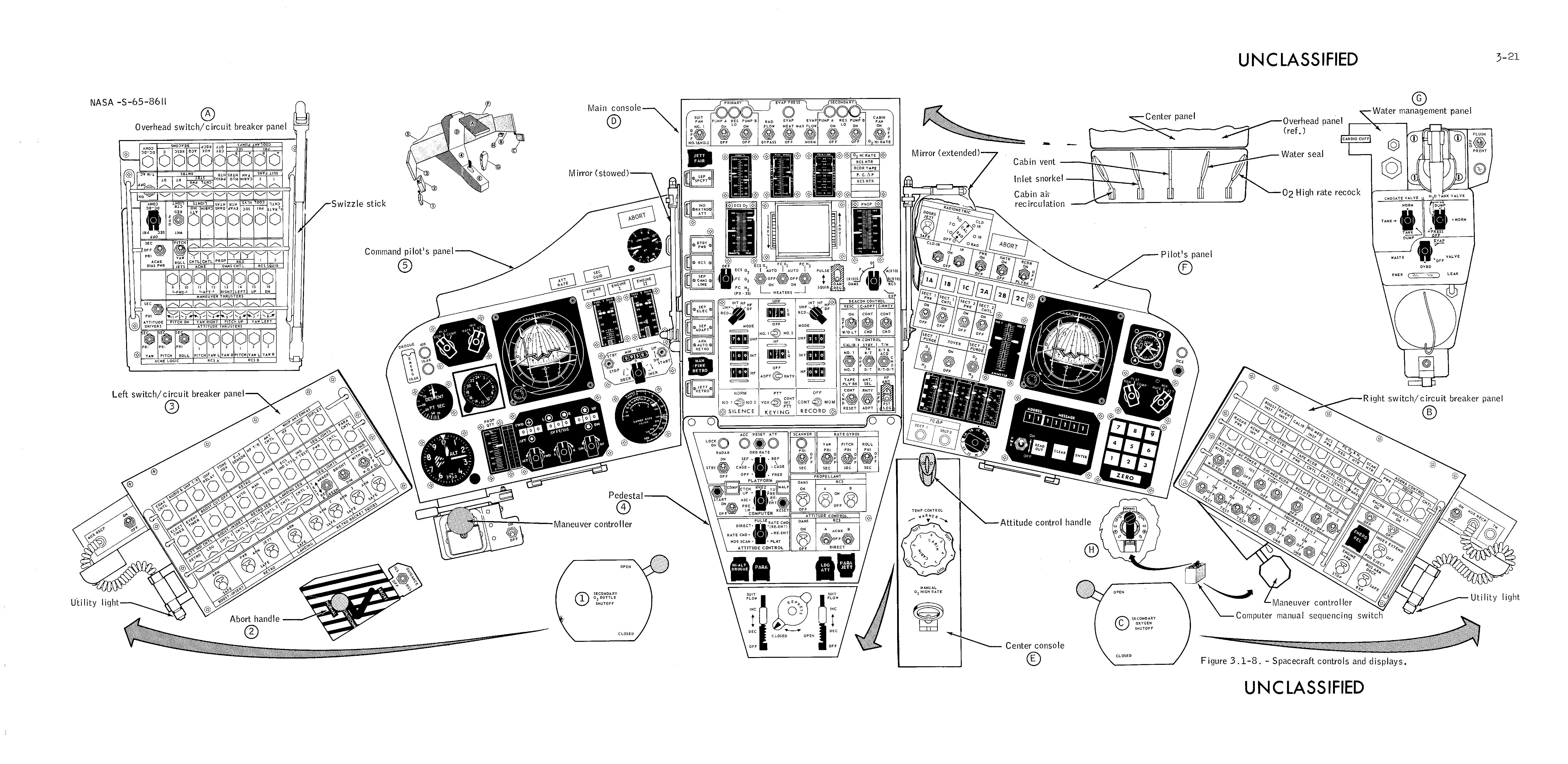 |
| Gemini Instrument Panels (http://www.ibiblio.org/apollo/Gemini.htp) |
Notice the swizzle stick on part "A" of the above image in the upper left. A brilliantly simple solution to a potentially serious problem.
Keep checking back for updates here on my blog. Once the Kickstarter launches I'll be refocusing my efforts on actually building the capsule and not preparing for the Kickstarter launch
Thursday, July 13, 2017
New Project: Open Source Gemini Simulator
Today I want to announce a new project I am starting: The Open Source Gemini Simulator.


This project will be to create a 1:1 scale replica of the Gemini Capsule, adapted for playing Kerbal Space Program. The capsule is designed to be made from readily available materials (Home Depot, Lowes, etc...) and can be made with general woodworking tools by anyone with a maker spirit! And since everything, the documentation, CAD files, drawings, software, and schematics, will all be Open Source anyone can make it! The project will be designed to be disassembled quickly into manageable components that can be transported and shown at events such as MakerFaire and Gaming Cons.
Below are a couple of graphics showing the finished structural design for the capsule:


The skin is not shown in these pictures to give a better view of all of the structural elements. I still need to layout all of the controls going into it. This will include mechanical 3 axis navballs, mechanical panel meters, and over 50 toggle switches. Almost every possible function of Kerbal Space Program will be controlled from this capsule. I'll be using kRPC to interface with Kerbal Space Program, and using Teensy 3.5 for the embedded electronics interface.
I'll be launching a Kickstarter in a couple days to raise funds for the project, check back soon to see when that gets launched! Once the project gets seriously underway, I'll be posting regular updates about the design work that has already been done and the future work as it progresses.
Tuesday, July 11, 2017
Welcome to my Maker Blog!
Welcome to venturesinmaking.com, the blog where I document my trials, tribulations, successes, and failures in my quest to make cool stuff. Check back often to see updates on various projects and their progress!
Subscribe to:
Posts (Atom)